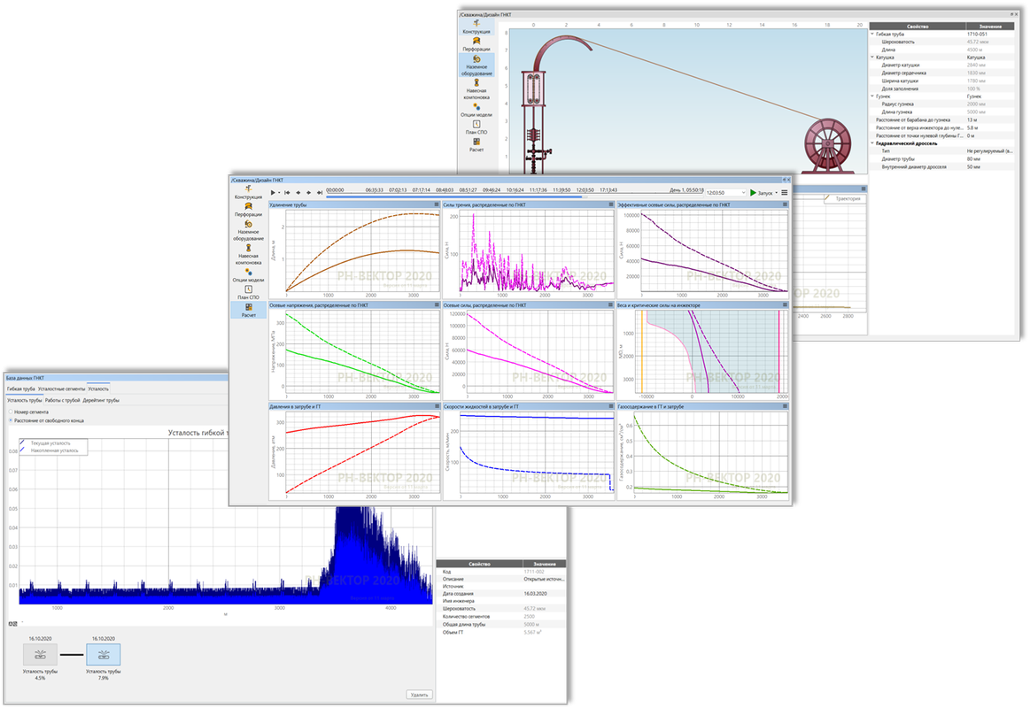
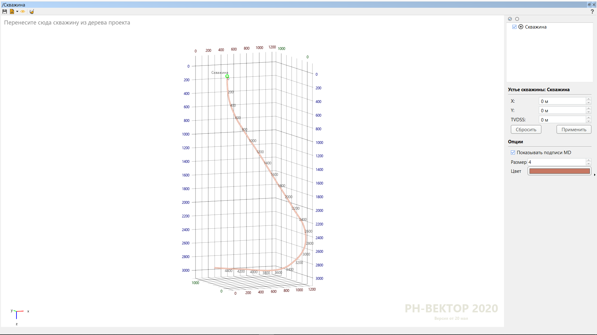
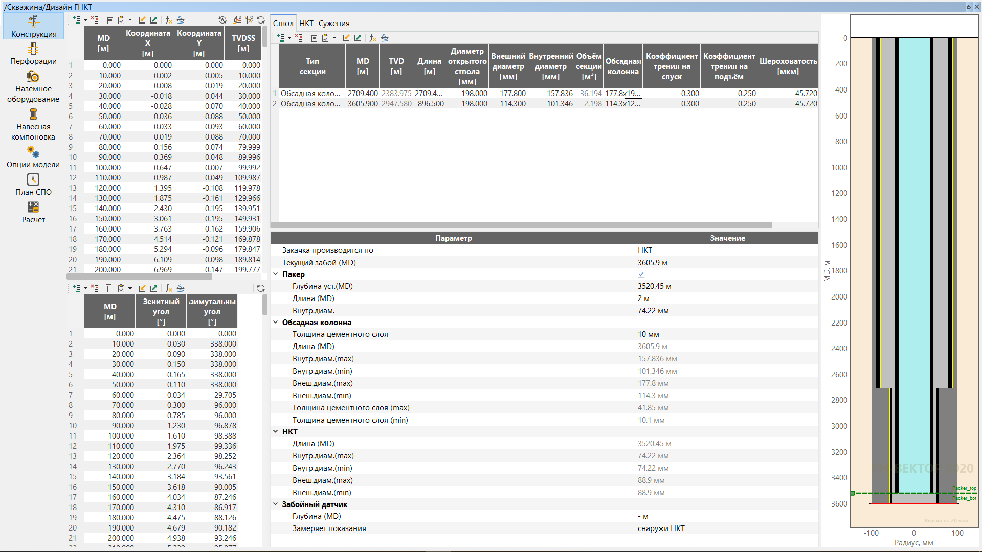
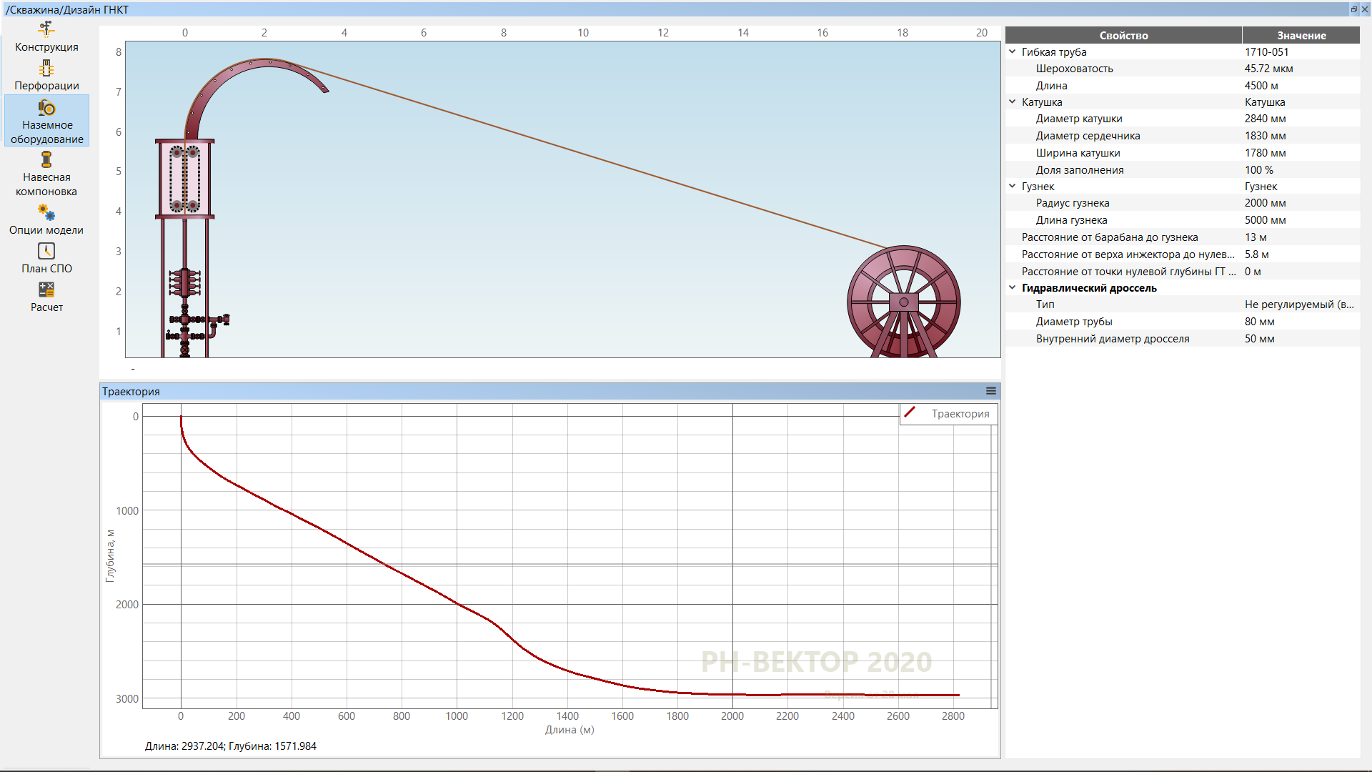
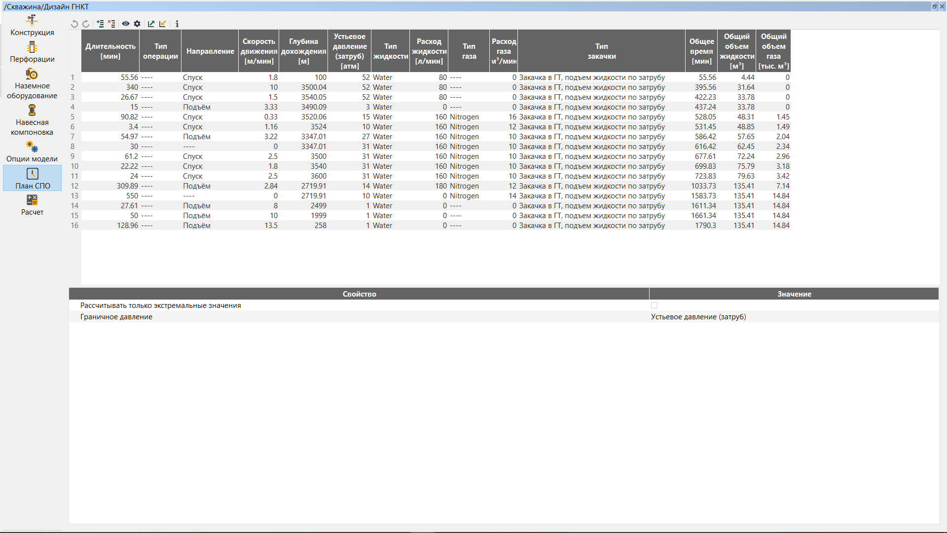
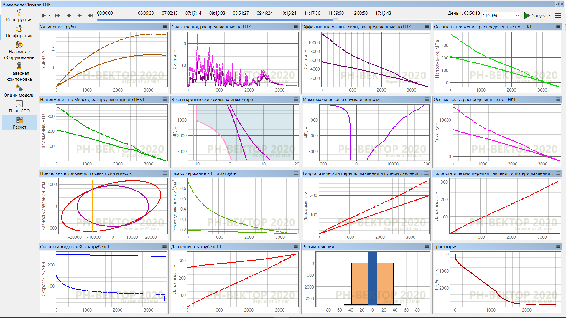
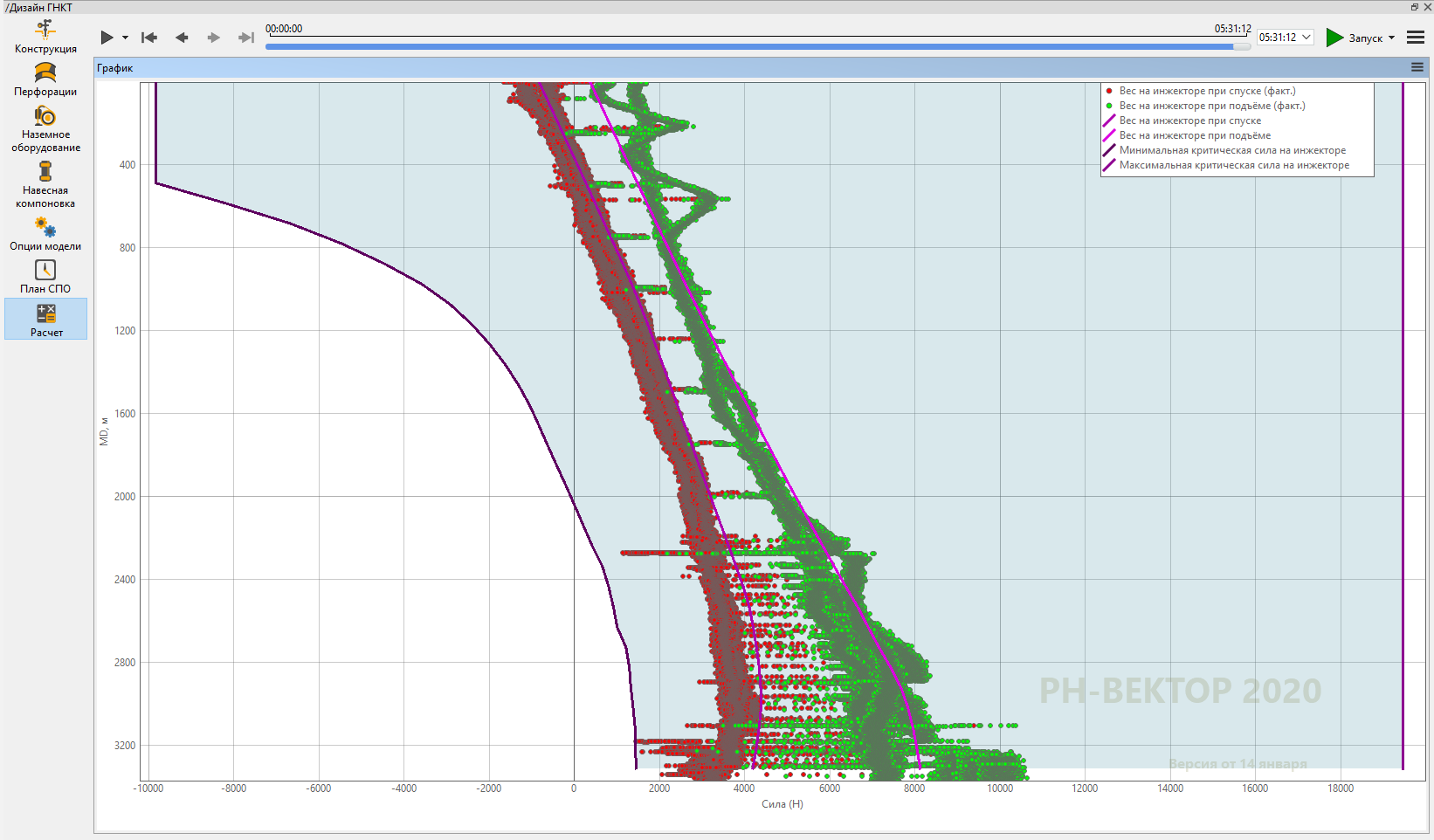
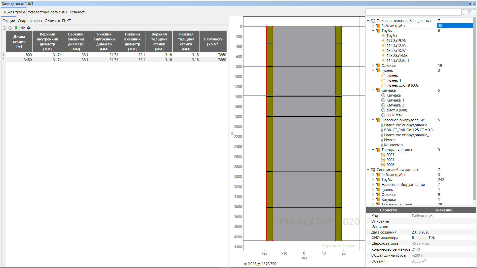
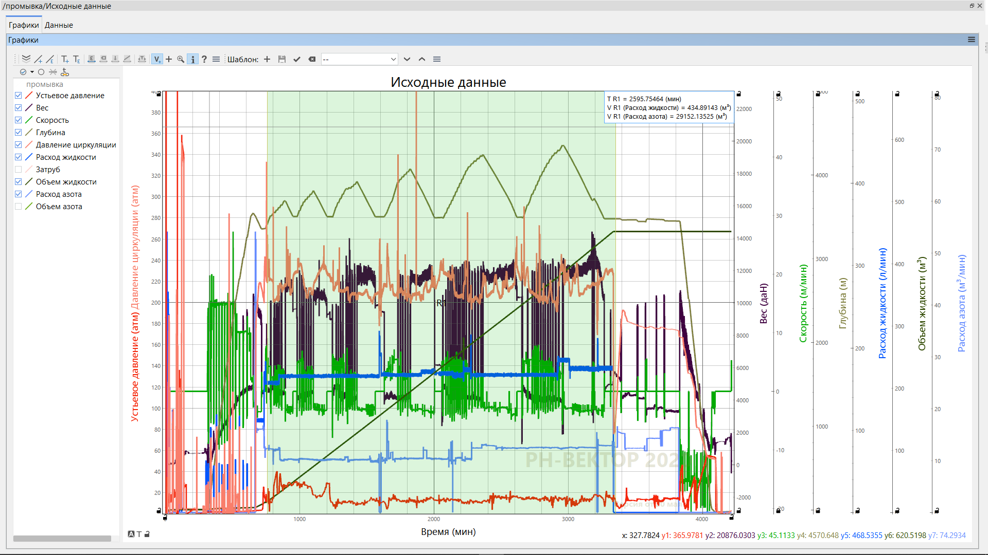
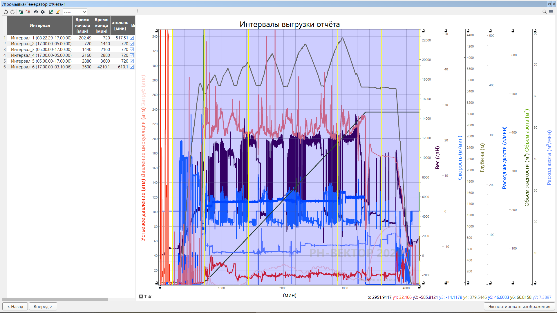
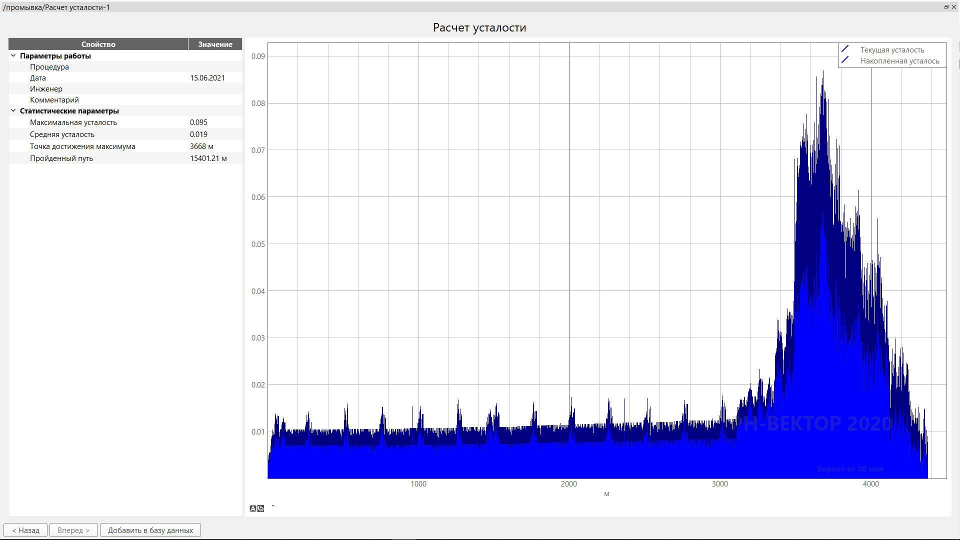
Coiled Tubing Simulator
RN-VECTOR is an industrial software for mathematical modeling and analysis of CT technological operations.
Software versions for Windows and Linux are availableInformation on the software price and purchase conditions will be provided upon requestListed in the Unified Register of Russian Programs for Electronic Computers and Databases